

- 873.88 KB
- 2022-04-22 11:28:35 发布

- 1、本文档共5页,可阅读全部内容。
- 2、本文档内容版权归属内容提供方,所产生的收益全部归内容提供方所有。如果您对本文有版权争议,可选择认领,认领后既往收益都归您。
- 3、本文档由用户上传,本站不保证质量和数量令人满意,可能有诸多瑕疵,付费之前,请仔细先通过免费阅读内容等途径辨别内容交易风险。如存在严重挂羊头卖狗肉之情形,可联系本站下载客服投诉处理。
- 文档侵权举报电话:19940600175。
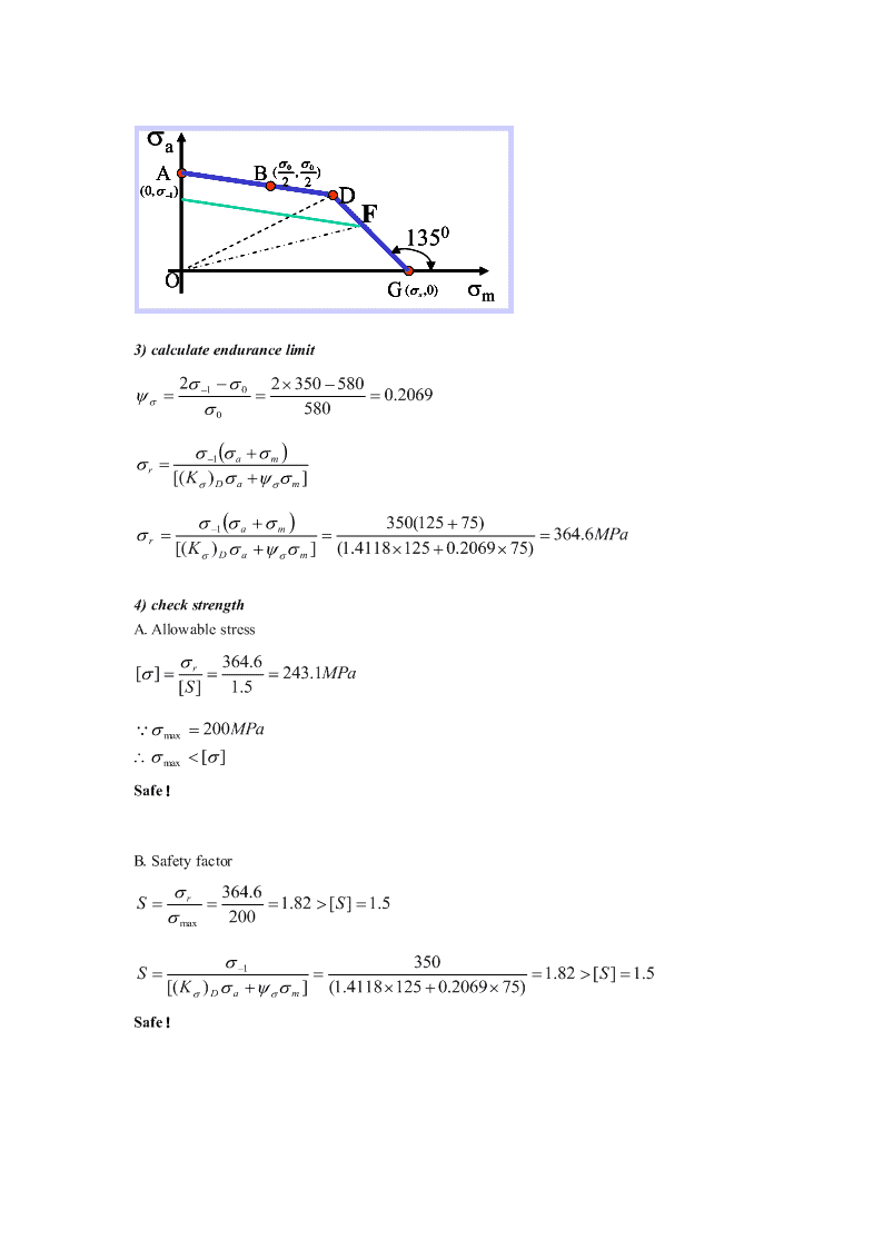
'2-4已知某钢制零件受弯曲变应力的作用,其中,最大工作应力max=200MPa,最小工作应力min=-50MPa,危险截面上的应力集中系数k=1.2,尺寸系数=0.85,表明状态系数=1。材料的s=750MPa,0=580MPa,-1=350MPa。试求:(1)绘制材料的简化极限应力图,并在图上标出工作应力点的位置;(2)求材料在该应力状态下的疲劳极限应力r;(3)按疲劳极限应力和安全系数分别校核此零件是否安全(取Smin=1.5)Analloysteelpartsuffersbendingstress:s=750MPa,0=580MPa,-1=350MPaWorkingstress:max=200MPa,min=-50MPak=1.2,=0.85,=1,(1)Makethestressendurancefigure,andfindtheworkingpoint.(2)Findthefatiguestresslimitationr.(3)Checkifthispartissafe,usingthefatiguestresslimitationandthesafetyfactor(ifSmin=1.5).Solution:1)calculatestressamplitude、meanstressandstressratio11(200(50))125MPaamaxmin2211(20050)75MPammaxmin22min50r0.25200max2)judgewheretheworkingpointisk1.2(K)1.4118D0.851((K)1)()D0s1s0r0[((K)1)2]sD01(1.41181)580750350(750580)=0.46750[(1.41181)5802350]rr0∴workingpointisinAOD
a00AB(,)22(0,)1DF1350OG(s,0)m3)calculateendurancelimit21023505800.206958001amr[(K)]Dam1am350(12575)364.6MPar[(K)](1.41181250.206975)Dam4)checkstrengthA.Allowablestressr364.6[]243.1MPa[S]1.5200MPamax[]maxSafe!B.Safetyfactorr364.6S1.82[S]1.5200max3501S1.82[S]1.5[(K)](1.41181250.206975)DamSafe!
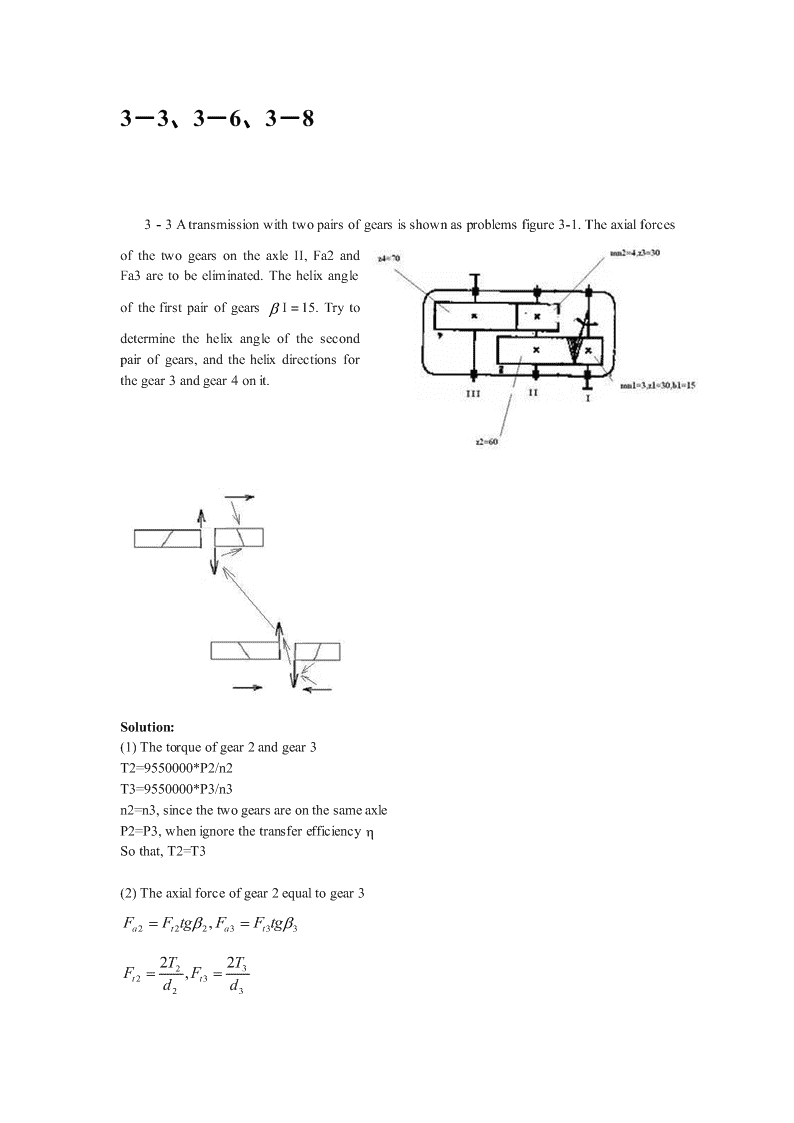
3-3、3-6、3-83-3Atransmissionwithtwopairsofgearsisshownasproblemsfigure3-1.TheaxialforcesofthetwogearsontheaxleII,Fa2andFa3aretobeeliminated.ThehelixangleofthefirstpairofgearsI=15.Trytodeterminethehelixangleofthesecondpairofgears,andthehelixdirectionsforthegear3andgear4onit.Solution:(1)Thetorqueofgear2andgear3T2=9550000*P2/n2T3=9550000*P3/n3n2=n3,sincethetwogearsareonthesameaxleP2=P3,whenignorethetransferefficiencySothat,T2=T3(2)Theaxialforceofgear2equaltogear3FFtg,FFtga2t22a3t332T2T23F,Ft2t3dd23
mzmzn22n33d,d(P54,Helicalgear,mnzmustbedividedbycos)23coscos33soTT23sinsin23mzmzn22n33mn3z30sinsin4*30*sin15/(3*60)32mzn22sin=0.17254630=9.94=956’24’’33-6Anenclosedtransmissionwithtwopairsofgears.Known:Fig3-22TransmissionwithtwopairofP1=20kW,n1=1430r/min.gearsGearratiou=4.3,onedirectionrotating.16hourperday,andlifeismorethan5years.Withlowerstiffnessshaftandslightimpactload.Material40Cr,withsurfacehardening.Hardness:48~55HRCCompletethedesignforthefirstpairhelicalgear.Solution:1)Determinetherequiredmaterialsandhardnessofthem.Computetheallowablestress.(1)Determinetherequiredmaterialsandhardness.40Cr,withsurfacehardening.Hardness:48~55HRC,anduse55HRC.(2)Computetheallowablestress.①Determinetheendurancelimitstress.σHlimandσFlimCheckthefig3-16(c),σHlim1=σHlim2=1200MPaCheckthefig3-17(c),σFlim1=σFlim2=360MPa②LifecyclenumberN.DeterminethelifefactorZN、YN8N60ant6011430(530016)20.05921011
8N120.0592108N4.7888102u4.3Fromfig3-18,ZN1ZN21.Fromfig3-19,YN1YN21.③Computetheallowablestress.Fromthetable3-4,S1.2,S1.5。HminFminZ12001Hlim1N11000MPaHP1S1.2HminHP2HP1Flim1YSTYN136021480MPaFP1S1.5FminFP2FP12)Fatiguetype,anddesigncriteriaHardsurface,enclosedgear.Basicfatiguetypeisteethbreakage.Designusingbendingfatiguestrength,andcheckthecontactfatiguestrength.3)Determinetheinitialdesignparameters.(1)Pinion’snominaltorque6P1620T9.55109.5510133566Nmm1n14301(2)GeartypeHelicalgear.(3)PrecisionclassClass7(4)Initialdesignparametersβ=12°,z1=30,z2=z1u=30×4.3=129,χ1=χ2=0,Fromtable3-6,ψd=0.5(5)Designforthebendingstress.Todeterminetheparametermn,theparametersbelowneedtobedecided.YFa1,YFa2,YSa1,YSa2,Yε,Yβ
Lowerstiffnessshaftandslightimpactload.Fromtable3—1,K=1.35。z30Equivalenttoothnumberz132.1v133coscos12z129z2137.8v233coscos12Fromfig3-14,YFa1=2.5,YFa2=2.21;Fromfig3-15,YSa1=1.65,YSa2=1.8;Yε=0.7,Yβ=0.9。YFa1YSa12.51.650.00859375480FP1YFa2YSa22.211.80.0082875480FP2Usingthebiggervalueforcalculating:22KT1cosYYYFaYSam3mmn2zd1FP221.35133566cos120.70.930.0085937520.530=1.607Fromtable3-7,thestandardmodulemn=2mmm2na(zz)(30129)162.55mm122cos2cos12Use:a=165mmAdjustthehelixangle:m(zz)2(30129)n12arccosarccos1529"55""2a2165Pitchdiameter:mz230n1d62.264mm1coscos1529"55"mz2129n2d267.746mm2coscos1529"55"
o(Notice:βfor××××’××’’;Pitchdiameterfor×××.××(d1+d2)/2=a=165mm)nd143062.26411v4.6620m/s6000060000Approximatelyequaltotheinitialvalue.Toothwidth:Gear:b2=b=ψdd1=0.5×62.264mm=31.132mmPinion:b1=b2+(5~10)=(31.132+6)mm=37.132mm4)CheckforthecontactstressFromfig3-11,Z2.43;Fromtable3-2,Z189.8MPa;Z0.8;HEZcoscos1529"55""0.9816Contactstress:2KTu11ZZZZHHE2bdu121.351335664.312.43189.80.80.9816237.13262.2644.3=695σHP1=σHP2=1200MPaSafe.5)Structuredesign,etc.3-8CheckthepowerP1forapairofbevelgears.
Givn:z1=18,z2=36,m=2mm,b=13mm,n1=930r/min.Electromotordriven,Withonedirectionrotatingandslightimpactload.Workinglife24000hours.Materialsteel45.Pinionquenchingandtempering.Hardness230~250HBS;Gearnormalizing.Hardness190~210HBSPrecisionclass8.Pinionaxlewithcantileverbeam.Highreliability.Solution:1)Determinetherequiredmaterialsandtreatmentofthem.Computetheallowablestress.(1)Determinetherequiredmaterialsandhardness.Materialsteel45.Pinionquenchingandtempering.Hardness230~250HBS,using240.Gearnormalizing.Hardness190~210HBS,using200.(2)Computetheallowablestress.①Determinetheendurancelimitstress.σHlimandσFlimCheckthefig3-16(b),σHlim1=600MPa;σHlim2=550MPaCheckthefig3-17(b),σFlim1=220MPa;σFlim2=210MPa。②LifecyclenumberN.DeterminethelifefactorZN、YN8N60ant601930(24000)13.39210118N113.382108N6.691102u2Fromfig3-18,ZN1ZN21.Fromfig3-19,YN1YN21.③Computetheallowablestress.Fromthetable3-4,S1.1,S1.4。HminFminZ6001Hlim1N1545.45MPaHP1S1.1Hmin550/1.1500HP2
YY22021Flim1STN1314.2857MPaFP1S1.4Fmin210*2*1/1.4300FP22)Fatiguetype,anddesigncriteriaSoftsurface,enclosedgear.Basicfatiguetypeispitting.Designorcheckthecontactfatiguestrengthmainly.(Ifthemoduleissmall,it’snecessarytocheckthebendingfatiguestrength.)3)Determinetheinitialdesignparameters.(known)Pinion’snominaltorquePPT9.5510619.55106110268.8172PNmm11n93014)CheckthecontactfatiguestressTodecideK、ZH、ZE.Electromotordriven,Withonedirectionrotatingandslightimpactload.Pinionaxlewithcantileverbeam.Highreliability.K=1.4.Fromfig3-11,Z2.5;Fromtable3-2,Z189.8MPa;HEBevelgear1:tg=18/36=0.5,sin0.4472,cos0.8944111d1==mz1=2*18=36R=(d1/2)/sin1=18/0.4472=40.2504ψR=b/R=13/40.2504=0.32304KT1ZZMPaHHE23HP0.8510.5duRR141.410268.8172P12.5189.8545.45230.850.323010.50.3230362(T1=4250Nmm)
P1=0.4139kW4-1、4-34-1Determinetheworm-geardrivesystem’srotatingdirectionsfortheaxles,wormgearhelixdirection,andtheforceslocationanddirectionforwormgear.Fig.problem4-11、3-worm;2、4-gear4-3DesignanArchimedeanCylindricalwormusinginacrane.Mediumimpactload.Wormaxlewithelectromotordriven.P1=10kW,n1=1470r/min,n2=120r/min.Workingwithintermission.2hoursoneday,andtheworkinglife10years.
Solution:1.Determinetherequiredmaterialsandtreatmentforthewormandthegear.Determinetheprecisionclass.Wormmaterial40Cr,surfacehardening.Hardness45~55HRC.GearMaterialZCuSn10P1,Sand-cast.Presetv2≤5m/s,andselecttheprecisionclass8(GB10085-88).2.AllowablecontactstressHPFromtable4-6,"200MPa.HPGearratioi=n1/n2=1470/120=12.2514707LifecyclenumberN60nt602300104.32102h12.25771010LifefactorZ880.833N7N4.3210"AllowablecontactstressZ0.833200166.6MPaHPNHP3.Determinethewormthreadnumberzandthegearteethnumberz.12z4;ziz12.254491214.Designforthecontactfatiguestrength.1)TorqueonthegearT2z4,estimate0.9.1610TTi9.551012.250.9716250Nmm2114702)LoadfactorKMediumimpactloadK1.2。A3)ElasticityfactorZESteelwormVs.Coppergear,Z160MPaE4)Determinem,dandd12
2ZE2md9KT()1A2z2HP1602391.2716250()2971.6mm49166.623Fromtable4-1,md31752971.6mm时,m6.3mm,d80mm,z4,111q12.698.dmz6.349308.7mm.225)Gearvelocityv2dn3.14308.712022v1.9m/s5m/s260100060000Accordwiththepresetvalue.6)Distancebetweenthetwocenters,a.a0.5(dd)0.5(80308.7)194.35mm127)Threadangleγz1m46.30arctan()arctan()1729"4"d8015.Checkthethermalbalance.1)SlidingvelocityvSdn80147011v6.4525m/sS060000cos60000cos1729"4"2)Equivalentfrictionanglev0Fromtable4-9,120"v3)Efficiency0tgtg1729"4"0.950.950.87800tg()tg(1729"4"120")v4)Heattransferareaa1.75194.351.752A0.33()0.33()1.0557m1001005)Workingoilthermal2Environmenttemperaturet0=20℃.HeatemittingfactorKt=15W/(m℃1000P1(1)100010(10.878)0tt2097t1opKA151.0557t
6.ResultanalysisWorkingtemperaturetisabovethepermittedvalue.Andsomeextraemittingequipmentmust1beadded.5-45-4DesignaV-beltdriveusinginacrusher.Given:ElectromotorY132S-4,P=5.5kW.n1=1440r/min,transmissionratioi=2.Doubleshift.Thedistancebetweenthetwosheavecentersislimitedto600mm.Solution:1)WorkingpowerPcDoubleshiftmeans16hoursperday.Fromtable5-6,theworkingfactoforcrusher:KA=1.4Pc=KAP=1.4(1.6)×5.5=7.7(8.8)kW2)ThetypeforV-beltPc=7.7kW,n1=1440r/min,Fromfig5-7,selecttypeA.3)Sheavediameterdd1anddd2Fromtable5-7,selectdd1=100mm,ε=0.02did(1)2100(10.02)mm196mmd2d1Fromtable5-7,selectdd2=200mm.4)Beltvelocityvdd1n11001440vm/s7.536m/s601000601000
Between5~25m/s.5)Distancebetweenthetwocentersa,andthebeltlengthLda0,initialvalue210mm≤a0≤600mmSelecta0=400mm(300,500arealsookay).2(dd)L2a(dd)d2d1d00d1d224a023.14(200100)2400(100200)24400=800+471+6.25=1277.25Fromtable5-5,SelectLd=1400(1250)mmTheactualvalueofaaa(LL)2400(14001277.25)2461(385)mm0dd06)Smallsheave’swrapangleα1dd200100180d2d157.318057.31671201a461(165>120)(okay)7)beltnumberd200dd1=100mm,id22.04,v=7.33m/s,d(1)100(10.02)d1Fromtable5-2,P0=1.31kWFromtable5-3,ΔP1=0.1kWα1=167°,Fromtable5-4,Kα=0.968Ld=1400mm,fromtable5-5,KL=0.96(0.93)PP7.7zcc5.80[P](PP)KK(1.310.1)0.9680.96000Lz=6.8)InitialtensionforceF0
F500(2.5K)Pcqv2500(2.50.968)7.70.17.3320Kzv0.96867.33=138.544+5.373=143.917N9)ForceexertingonshaftFQ167F2zFsin126144sin1717NQ02210)Structuredesign.6-4(p152)6-4Atransmissionsystemisshownbelow.Vbelt,horizontal,forceQ=3000NThetransmissioninputaxial,T=510NmoWiththepiniond1=132.992mm,1=1210’38’’,b1=120mmThematerialissteel45.Initiallyselecttherollingbearing7300C.(1)Finishtheshaftstructurefigure.(2)Determinethediameteroftheshaft,usingthestresscombinationofbendingandtorque.(3)Thencheckthesafetyfactorforthefatiguestrength.
Notice:1)轴承型号7300C指内径未定;2)按比例画出轴系装配图,不画轴承座及轴承盖;3)注意轴的转向及各分力的方向。Solution:1.SelecttheshaftmaterialSteel#45,quenchingandtempering.FromTable6-1,650MPa,360MPabsFromTable6-4,b650MPa,then[σ-1]b=60MPa.2.Calculatetheforcesandmoments1)Gearforcesod1=132.992mm,T=510Nm,1=1210’38’’ThentheGearforceshouldbe:2T2510000FN7669.6Ntd132.992tgtg20nFF7669.6N2855.8Nrtcoscos1210"38FFtg7669.6tg121038N1655.0Nat2)Forcescalculatingfigure(Forcesdirections)
3)Calculatethebearingreactionforces,andmomentInhorizontalplane,Rha=3096.8N,Rhb=-3241NPointc,Leftside,M"R100/1000=3096.8×100/1000N=309.68NmH(c)HARightside,M"309.68(1655.066.496/1000)309.68110.05419.73NmH(c)(=3000×(250+160)/1000-3241×250/1000=1230-810.25=419.75)Pointb,M3000160/1000480NmH(b)Inverticalplane,Rva=5478.3N,Rvb=2191.3N
Pointc,MR100/1000=5478.3×100/1000N=547.83Nmv(c)VA3.Usingthecombinedstrengthtoestimatetheminimumdiameterofshaft1)Calculatethecombinedmoment22BendingmomentMMMHVPointc,leftside2222M"MM309.68547.83Nm629.3Nm(c)H(c)V(c)Pointc,rightside2222M"MM419.73547.83Nmm690.1Nmm(c)H(c)V(c)Torqueisperformedbetweenc-d.
2)Calculatetheequivalentmoment(combiningmomentandtorque)22MM(T)caSet0.6Pointc,rightside2222MM(T)690.1(0.6510)Nmca(c)(c)=754.9NmPointb,2222MM(T)480(0.6510)Nmca(b)(b)=569.24Nm3)Determinetheminimumdiameter,usingthecombinedmomentThepointcandpointdarethepotentialdangerouspoint.3FromTable6-2,W≈0.1d,fortheroundshaft.Thenforpointb(theminimumdiameter)M569.241000d3camm3mm45.6mm0.10.1601bM754.91000(Forpointc,d3camm3mm50.1mm)0.10.1601bThensetthediameterforthesectionb-d(Vbeltsheave)for50mm.4.StructuredesignfortheshaftThemainelementsmountedontheshaftincludethegear,Vbelt,andtherollingbearings.ThediameterfortheVbeltsheave,d=50mm.(lengthislessthan140mm,set136mm.)ThenthelocatingshoulderfortheVbeltsheavemustbe5-10mmmorethan50mm,andset57mm.Thediameterforthebearingisnon-locatingshoulder,2-4mmmorethan57mm,andset60mmforthebearinginnerdiameter.Andselect7312Cbearing.(fromthemanualin机械设计课程设计》,theinnerdiameter60mm,outerdiameter130mm,width31mm.)Thegearinnerdiameter,set65mm.(lengthislessthan120mm,set116mm.)Andtheshoulder75mm.
5015515510116607075656057136503131100250160----------5.CheckthesafetyfactorCrosssectionb-bisillustratedasfollowingBendingstress:M480000a325.9MPaW57/100mTorsionalstress:T5100006.9MPaa32W257/5T6.9MPama650MPa,360MPabsFromtheTable6-1,0.20.1Stressconcentrationstressfromattachedtable6-1k1.825k1.625Surfacequalityfactorandscalefactorfromattachedtable6-5and6-4
0.92(650MPa,R1.6m)0a0.84=0.78Then3001S4.9k1.82525.9am0.840.921551S9.5k1.6256.90.16.9am0.780.92SSS4.3S1.5ca22SSSocrosssectionb-bissafe.7-3(p181)7-3Designaradialhydrodynamicplainsurfacebearinginamotor.RadialloadF=60kN,od=160mm,n=960r/min,wrapangle180,theloadisstable.Thebearingmustbesplithorizontallywheninstallation.Solution:1.BearingstructureHorizontalsplitstructure,wrapangleis180°2.DeterminethewidthFromForm7-4,formotorl/d=0.6~1.5,Specifyl/d=1.0Sowidthl=(l/d)×d=1.0×160=0.16m3.Calculatep,v,andpvF60000p2.344MPadl0.160.16dn3.14160960v8.04m/s60100060000pv2.3448.0418.84MPam/s4.ChoosematerialofbearingBasedonp,v,andpvfromTable7-2,selectZCuPb30,HBS=25
Table7-25.Chooseparameters0Suppose:tm50CSelectoil:L-AN32SofromFigure14-2Figure14-2γ=20mm2/sη=γr=20×10-6×900=30.2530.25(0.6~1)10v(0.6~1)1031.4(0.00142~0.00237)
Adopt:ψ=0.00196.ChecktheminimumoilfilmthicknessSurfacefinishRz1,Rz2Table7-5Table7-5selectRz1=3.2mm,Rz2=3.2mmLoadfactorCP22F600000.0019C4.677P2vl20.0188.040.16FromFigure7-16,l/d=1,CP=4.677,soselect=0.85Figure7-16dh(1)800.001910.850.0228mmmin2Safetyfactor:h0.0228minS3.562RR0.00320.00321Z2ZTherequirementoftheminimumoilfilmthicknessissatisfied.7.Calculatetheoiltemperature
FromFigure7-16frictionfactorCf=1.0Figure7-16FromFigure7-17fluxfactorCQ=0.13Figure7-17CfF1.023440000t10.88C803.14scC17009000.13Qv0.00198.04Averageoiltemperature:t10.8800tt4045.44C50Cm122Sotheoiltemperatureissuitable.Fromtheaboveresultsthedesignispracticable.
8-2(p213)8-2Apairofangularcontactballbearingsareinstalledfacetoface,withthenominalcontactoangle=15.d=35mm,n=1800r/min,mediumimpact.Fr1=3390N,Fr2=1040N.AxialloadFA=870N.Determinetheexpectedworklifeforthebearings.12FAFFr1r2Solutions1.Selectthebearingtypeandcodeinitially.Angularcontactballbearing,withd=35mm.Soselect7307Cinitially.Fromthedesignmanual(<机械设计课程设计>p119,Form12-6):C0r=26800N,Cr=34200NFromForm8-8:fp=1.5(mediumimpact);FromForm8-5:ft=1.0(normally).2.Calculatethederivedaxialforce.FromForm8-9,thederivedaxialforceS=0.5Fr.Thenthederivedaxialforceforthebearing1and2:S1=0.5Fr1=0.5×3390N=1695NS2=0.5Fr2=0.5×1040N=520N3.CalculatetheaxialloadFaforthebearing1and2.Thebearingsareinstalledfacetoface.FaS1S2S2+FA=520+870=1390P2,Usingbearing1forthecalculating.Fortheballbearingε=3.Fromtheequation(8-4)得66310ftCr10134200Lhh2209h60nP16018005514(Ifthelifeisnotlongenough,trytochoose7307AC)'
您可能关注的文档
- 《机械制造技术基础》复习题答案.doc
- 《机械制造装备设计》关慧贞第三版课后习题答案.doc
- 《机械制造装备设计》关慧贞第三版课后习题答案.pdf
- 《机械原理》(武汉大学)课后习题参考答案.doc
- 《机械原理》复习题及答案.doc
- 《机械基础》习题答案.doc
- 《机械工程测试技术基础》(第三版熊诗波_黄长艺)课后习题及答案详解.doc
- 《机械工程测试技术基础》第三版课后习题答案.pdf
- 《机械工程测试技术基础》课后习题及答案详解.doc
- 《机械设计》(第八版)课后习题答案(全共32页).doc
- 《机械设计基础》试题及答案.doc
- 《机械设计基础》课程课后作业.doc
- 《机电传动控制》第五版课后习题答案.pdf
- 《机电传动控制》练习题及答案(1).doc
- 《材料性能学》习题答案.pdf
- 《材料成型工艺基础》部分习题答案.doc
- 《材料成形工艺基础》第2版课后习题答案(柳秉毅).pdf
- 《材料物理性能》课后习题答案.doc
相关文档
- 施工规范CECS140-2002给水排水工程埋地管芯缠丝预应力混凝土管和预应力钢筒混凝土管管道结构设计规程
- 施工规范CECS141-2002给水排水工程埋地钢管管道结构设计规程
- 施工规范CECS142-2002给水排水工程埋地铸铁管管道结构设计规程
- 施工规范CECS143-2002给水排水工程埋地预制混凝土圆形管管道结构设计规程
- 施工规范CECS145-2002给水排水工程埋地矩形管管道结构设计规程
- 施工规范CECS190-2005给水排水工程埋地玻璃纤维增强塑料夹砂管管道结构设计规程
- cecs 140:2002 给水排水工程埋地管芯缠丝预应力混凝土管和预应力钢筒混凝土管管道结构设计规程(含条文说明)
- cecs 141:2002 给水排水工程埋地钢管管道结构设计规程 条文说明
- cecs 140:2002 给水排水工程埋地管芯缠丝预应力混凝土管和预应力钢筒混凝土管管道结构设计规程 条文说明
- cecs 142:2002 给水排水工程埋地铸铁管管道结构设计规程 条文说明